Create Menu
Enables the user to create different scene elements that can add value to 3D scenes.
Lights
Point Light
Creates a spherical Light Source geometry and adds it to the scene. Point lights can be moved and positioned, using any of the move draggers. In the image below three point lights were added to the scene, and were snapped to the side lamps’ geometries using the Snap To Object tool in the Object task bar. Fine positioning was also done using the Move 3D tool.
The light properties can be found in the Properties Panel, to the right of the 3D area. There the user can edit the light properties, like changing its color, or its power.
Area Light
Depending on the effect the user needs, this is another light type that can be used. Same as Point lights, area lights have parameters that the user can change in the Properties Panel.
Spot Light
Spot Light is another light type that can be created in SimLab VR Studio. In addition to the main light properties, spot lights have Cone Angle property that sets the angle of the light.
Directional Light
Directional lights are for exterior scenes. The user can change the direction of the light but not its location. Other parameters for this light include, light Color, light Power, and light Name.
IES Light
Shapes
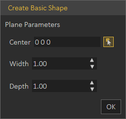
Plane: creates a 2D Plane, at Center coordinates entered in the first field. Width and Depth values determine the size of the created plane.
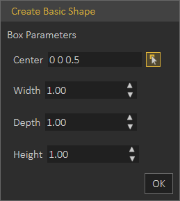
Box: creates a 3D Box, at Center coordinates entered in the first field. Width, Depth, and Height determine the size of the created box.
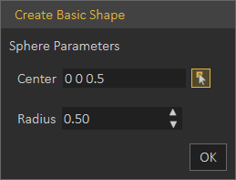
Sphere: creates a 3D sphere, at Center coordinates entered in the first field. Radius determines the size of the created sphere.
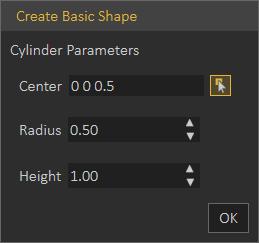
Cylinder: creates a 3D Cylinder, at Center coordinates entered in the first field. Radius and Height determine the size of the created cylinder.
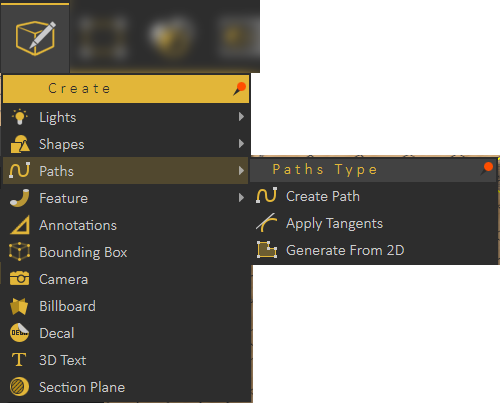
Paths
Create Path
Paths created in SimLab VR Studio can be from points in 3D space or on a plane. So when clicking the Create Path option, the Path Creation dialog will open, for the user to pick 3D or planer path.
Pick Points on a plane will display 3D access in the 3D area for the user to pick the plane to draw the path on.
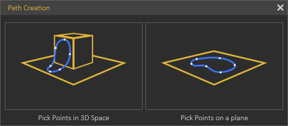
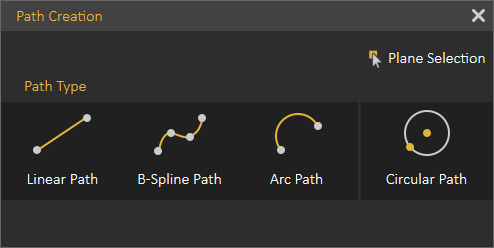
Both options will open the Path Creation dialog shown below, where the user can create different types of paths.
Apply Tangents
One of the points of a created path should be selected, before choosing this option. The program will ask for picking a point and normal to determine the tangent. So picking a point will modify the location of the picked path point to become tangent to the selected point.
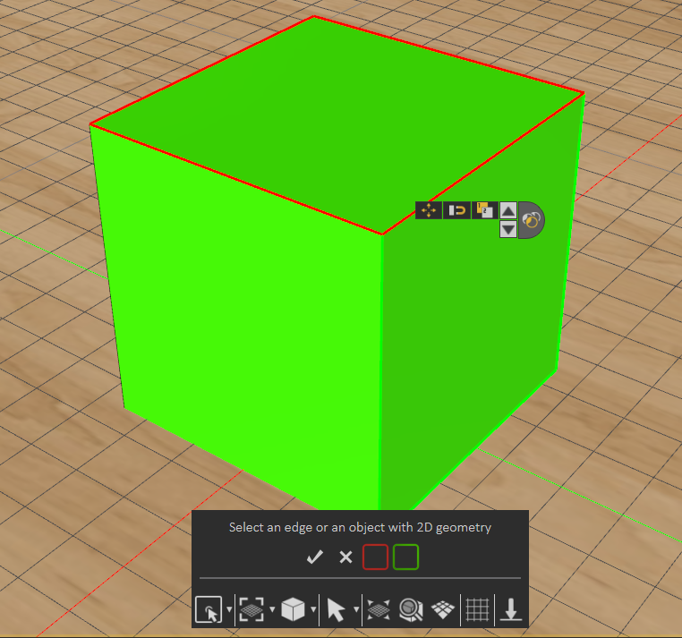
Generate From 2D
Creates 2D path from the outline of a selected surface. Using the Select options from the Common Tool bar can help in selecting a face, like selecting Pick Edge loop, as shown in the image below.
Feature
Features created in SimLab VR Studio allow the user to perform basic modifications and improvements to 3D models in order to improve the realism of 3D scene without needing to revert to a CAD application.
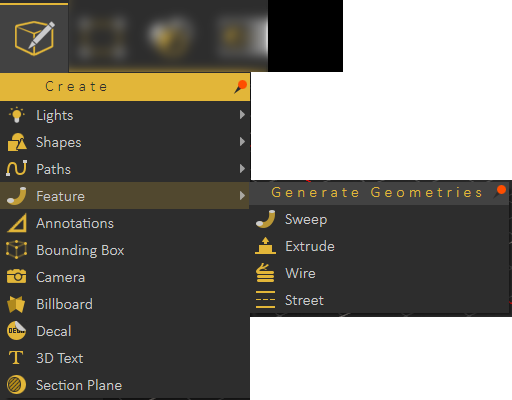
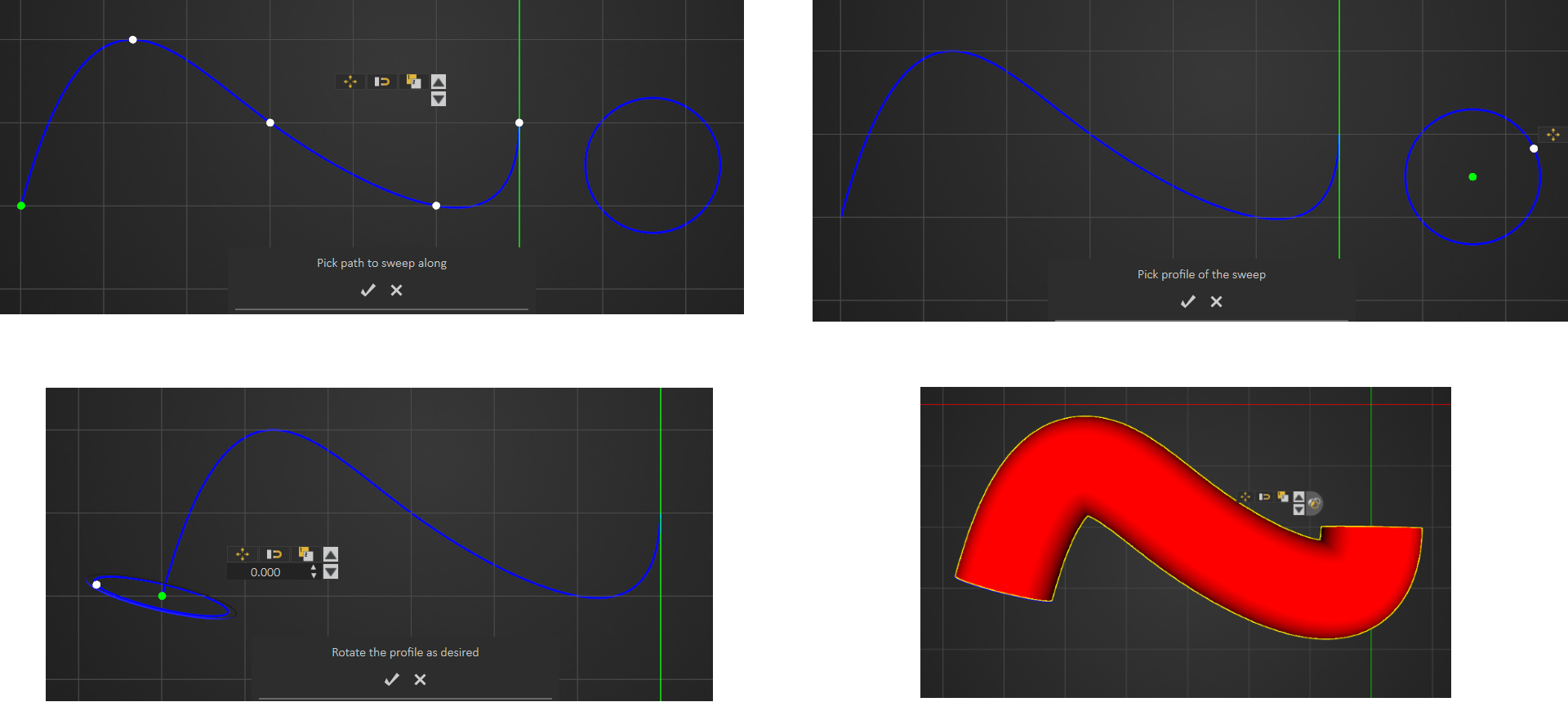
Sweep
This feature enables users to extrude a shape along a created path. After creating the path and shape, select Sweep form the menu, and start b picking the path to sweep along as the message indicates. Next select the profile to sweep, and rotate the profile as desired then click to create sweep.
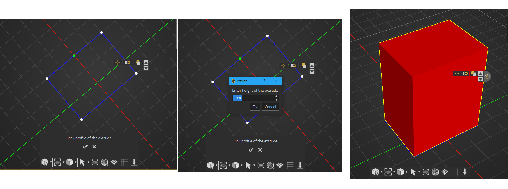
Extrude
Create a closed 2D shape, then in the extrude window enter the height, and a 3D object will be created. If an open 2D shape is used the created model will be hollow.
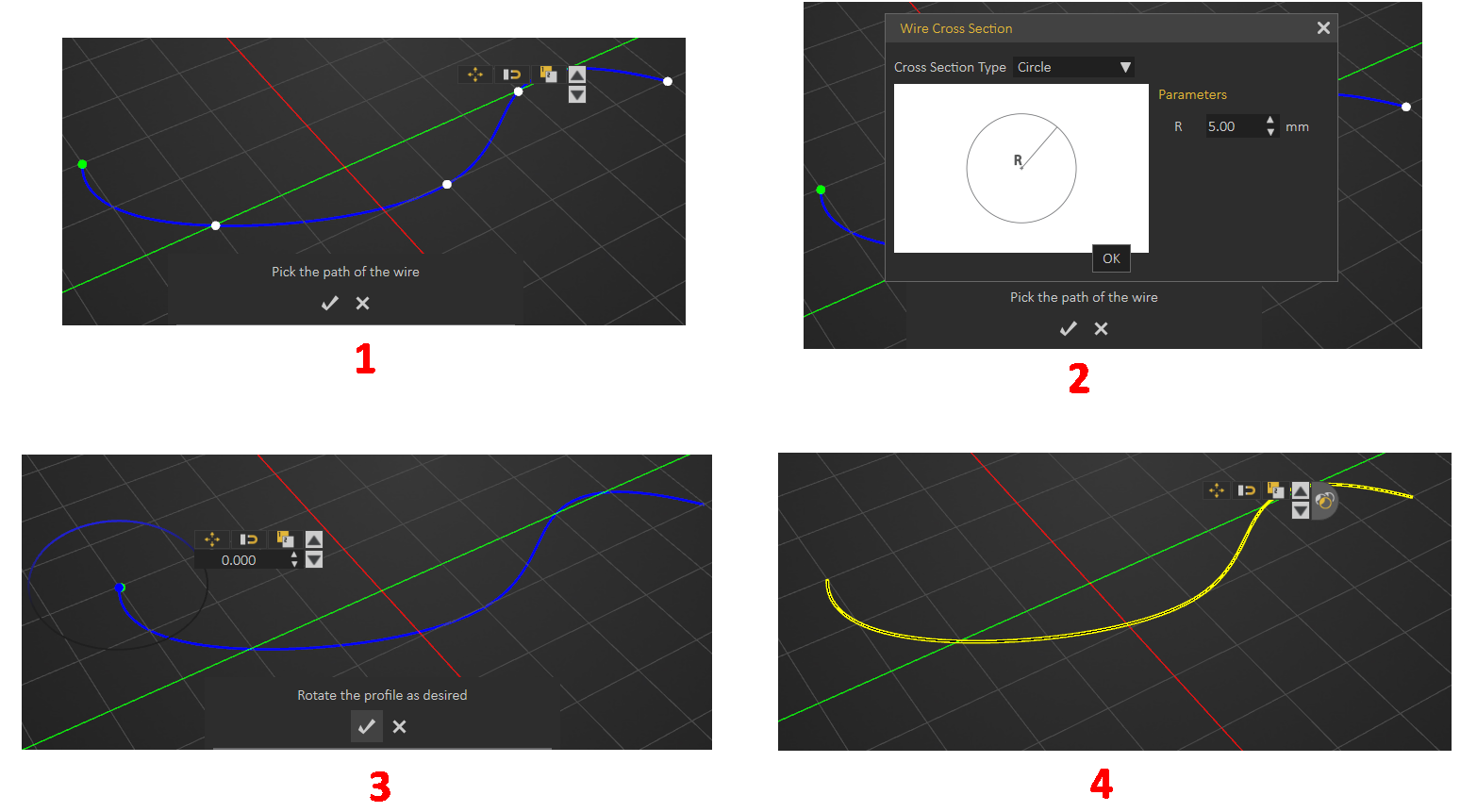
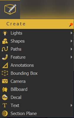
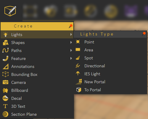
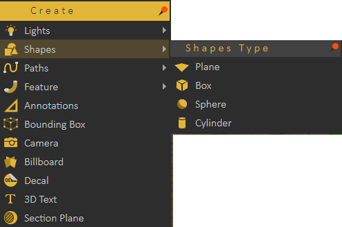
 Wire
Wire
 Wire
WireA path should be created first for the wire to follow, then the steps are as shown below.